
Advanced Materials: Electrochemical Sintering Enables Stress-Lensed Silicon Anodes for Long-Life All-Solid-State Batteries Validated by IEST SPFT2000


Abstract
The stress-lens electrochemical sintering (SLES) strategy, reported by Tianze Xu, Qingdong Gao and co-authors from Tianjin University and Tsinghua University in Advanced Materials (DOI: 10.1002/adma.74090), transforms the detrimental ~300% volume expansion of silicon anodes in all-solid-state batteries into a constructive electrochemical sintering force. By depositing amorphous silicon at the high-curvature pore openings of a porous carbon host, the pore geometry concentrates lithiation-induced stress precisely at interparticle contacts — a mechanism validated using the IEST SPFT2000 Single-Particle Mechanical Testing System. The resulting selectively sintered Si network delivers ~100% capacity retention after 100 cycles in half-cells and maintains over 60% capacity after 700 cycles in NCM532-based full cells, fundamentally resolving the conflict between mechanical stability and ionic transport in high-capacity alloy anodes.
📄 Source Paper
Tianze Xu1,2,3, Qingdong Gao1,2,3, Quan-Hong Yang1,2,3,8*, Shichao Wu1,2,3,8*, Ziyun Zhao1,7* et al.
DOI: doi.org/10.1002/adma.74090
| Journal: Advanced Materials
| Institutions: Nanoyang Group, Tianjin University of Advanced Carbon and Energy Materials Laboratory, Tsinghua University,
✓ IEST SPFT2000 Single Particle Mechanical Properties Test System used in this research
1. The Silicon Anode Dilemma in All-Solid-State Batteries
All-solid-state batteries (ASSBs) offer a transformative pathway toward safer, higher-energy-density energy storage. Among candidate anode materials, silicon stands out with a theoretical specific capacity of ~3,579 mAh g⁻¹ — nearly ten times that of graphite. However, the lithiation of silicon to form LiₓSi alloys induces a volumetric expansion exceeding 300%, which triggers cascading failure mechanisms at the electrode level.
Electrochemical Sintering — The stress-driven fusion of adjacent active-material particles during electrochemical cycling. In silicon anodes, repeated lithiation/delithiation creates mechanical stress that drives atomic rearrangement at particle contacts, forming sintered necks that can either restore (if controlled) or disrupt (if uncontrolled) ionic connectivity.
This volume change manifests in three interconnected degradation modes: (1) particle pulverization — repeated alloying/de-alloying generates internal stress that fractures individual Si particles; (2) solid–solid interface disconnection — the expanding and contracting Si network loses physical contact with the solid electrolyte, creating dead zones where ion transport is blocked; and (3) electrode-level structural collapse — cumulative particle rearrangement and fracture lead to macroscopic electrode cracking and loss of percolation. These problems are fundamentally exacerbated by an intrinsic electrochemical process: during cycling, neighboring Si particles undergo electrochemical sintering, gradually fusing together. While controlled sintering could theoretically restore ionic connectivity, uncontrolled sintering produces oversized agglomerates that magnify stress concentrations and accelerate electrode fracture.
2. Static Constraints Cannot Resolve Dynamic Evolution
Conventional approaches to managing Si volume expansion rely on static mechanical constraints — primarily carbon encapsulation and rigid ceramic coatings. These methods operate on the principle of physical confinement: a mechanically rigid shell (typically carbon or oxide) surrounds each Si particle, physically limiting its outward expansion.
Two representative strategies illustrate the fundamental limitation:
Non-electrochemical sintering (NES): A continuous carbon layer fully encapsulates each Si particle, physically separating adjacent Si domains. While this prevents uncontrolled agglomeration, the carbon interlayer introduces a substantial barrier to interparticle Li⁺ transport, producing poor rate capability and high interfacial resistance.
Carbon-coating delayed sintering: A thin carbon shell temporarily suppresses sintering, but after repeated cycling the shell fractures under cumulative stress, exposing bare Si surfaces that then undergo uncontrolled agglomeration — ultimately producing the very electrode cracking the coating was designed to prevent.
These limitations reflect a deeper design principle: static electrode architectures are fundamentally mismatched to the dynamic behavior of high-volume-change alloy anodes. What is needed is a mechanism that guides — rather than suppresses — the dynamic evolution of the silicon structure during cycling.
3. Introducing the Stress-Lens Electrochemical Sintering (SLES) Strategy
Stress-Lens Electrochemical Sintering (SLES) — A geometry-guided strategy in which amorphous silicon is conformally deposited at the high-curvature pore entrances of a porous carbon host. During lithiation, these constricted pore openings act as “stress lenses” that concentrate volumetric expansion stress precisely at interparticle contact points, lowering the atomic diffusion barrier and inducing selective, local electrochemical sintering to form a continuous, percolating Si network while preserving internal voids for volume buffering.
Professor Yang Quanhong’s team at Tianjin University, in collaboration with Dr. Zhao Ziyun at Tsinghua Shenzhen International Graduate School and co-authors, introduced a conceptual shift: instead of preventing electrochemical sintering, use geometric design to control where and how it occurs. The SLES strategy deposits amorphous silicon into the high-curvature pore entrance regions of a porous carbon matrix. During the initial lithiation cycles, these geometric constrictions act as stress lenses — concentrating the mechanical expansion stress at precisely the locations where interparticle sintering is desired.
This focused mechanical energy locally reduces the atomic diffusion barrier for Si rearrangement, promoting the formation of robust, selective sintered connections between adjacent Si domains while maintaining internal porosity to accommodate future volume changes. The outcome is a self-organized, percolating Si network that is simultaneously mechanically robust and ionically conductive — a feature that static encapsulation strategies cannot achieve.
4. Four Design Paradigms of Silicon Anodes
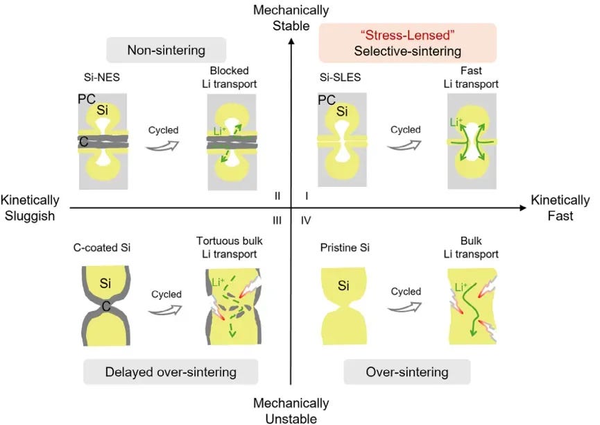
Figure 1. Four design paradigms of Si anodes for all-solid-state batteries, organized by mechanical constraint type (static vs. dynamic) and sintering control (suppressed vs. guided). Quadrant I (SLES, this work): Dynamic stress guidance — porous carbon pore openings act as stress lenses to induce selective electrochemical sintering, achieving both mechanical stability and fast Li⁺ transport. Quadrant II (Non-electrochemical sintering): Static constraint by full carbon coating that physically isolates particles but blocks interparticle Li⁺ conduction. Quadrant III (Carbon-coating delayed sintering): Static constraint that only temporarily inhibits sintering; shell fracture at later cycles triggers uncontrolled agglomeration. Quadrant IV (Uncontrolled pure-Si sintering): No constraint — severe agglomeration and electrode cracking under unrestrained volume expansion.
Figure 1 presents four design paradigms for silicon anodes, comparing static constraint versus dynamic stress‑guided approaches. The first quadrant shows the stress‑lens‑induced selective sintering architecture of this work: porous carbon pore openings act as stress-lensed, inducing directional sintering between particles and simultaneously achieving mechanical stability and fast Li‑ion conduction. The second quadrant depicts a non‑electrochemical sintering structure, where carbon layers isolate silicon particles to buffer expansion, but these layers suffer from poor ionic conduction and uneven stress distribution. The third quadrant corresponds to a carbon‑coating structure that delays excessive sintering—it only suppresses sintering temporarily; after cycling, the carbon layers crack and particle agglomeration blocks ion‑transport pathways. The fourth quadrant shows pure silicon with uncontrolled sintering: without constraint, silicon severely agglomerates, intensified strain causes electrode fracture, and long‑range conductive networks completely collapse. This comparison directly demonstrates that conventional approaches cannot simultaneously satisfy both stability and kinetics, highlighting the novelty of the present strategy.
5. Synthesis and Multi-Scale Structural Characterization
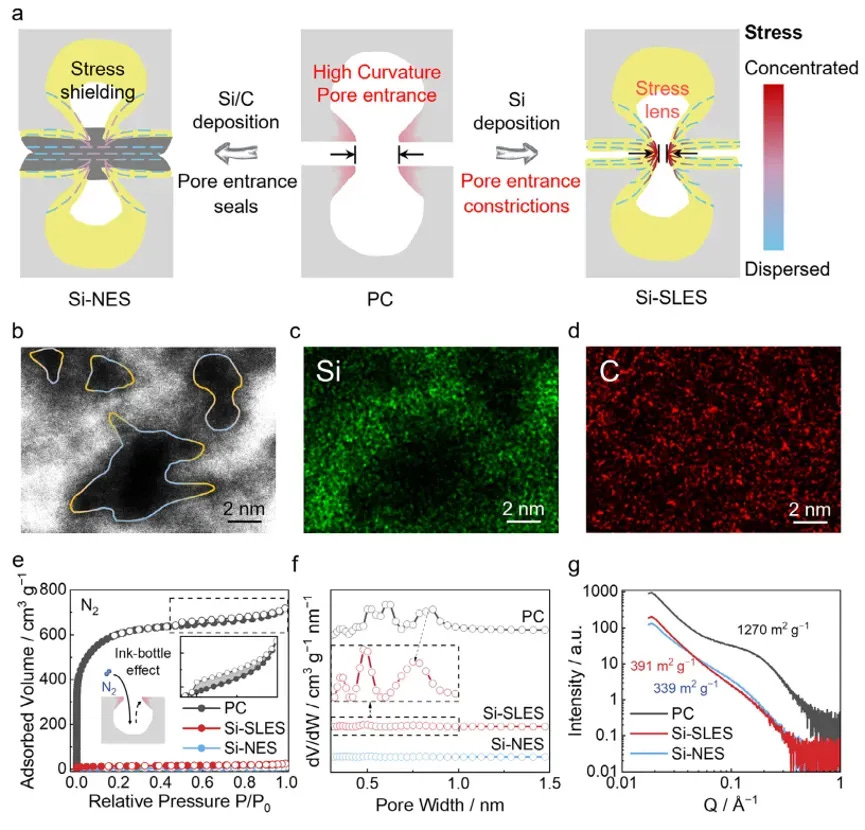
Figure 2. Synthesis route and structural characterization of the SLES architecture. (a) Schematic comparison of Si-SLES (Si deposited at pore entrances) versus Si-NES (continuous outer carbon coating). (b) Spherical aberration-corrected STEM with Si/C EDS mapping confirming uniform Si distribution at pore openings in SLES versus a continuous carbon film in NES. (c) N₂ adsorption-desorption isotherms and pore size distribution showing the high-curvature ink-bottle pore structure of the porous carbon host. (d) Small-angle X-ray scattering (SAXS) confirming that both SLES and NES retain internal void volume for Si expansion buffering.
The SLES composite was synthesized by selecting a porous carbon host with a high density of ink-bottle-shaped pores — narrow neck openings with wider internal cavities. Amorphous silicon was deposited via chemical vapor deposition, with process parameters tuned to concentrate Si selectively at the pore neck regions rather than filling the internal cavities. The control sample (Si-NES) was prepared by applying an additional full-surface carbon coating, producing a continuous outer carbon shell that physically isolates all Si domains.
Nitrogen adsorption analysis confirmed that the SLES sample retained a substantial population of open micropores after Si deposition — direct evidence that the internal void volume was preserved. In contrast, the NES sample showed near-complete closure of micropores after the outer carbon coating step. This structural difference is critical: the retained internal pores in SLES provide the physical space needed to accommodate the ~300% Si volume expansion during lithiation, preventing the stress buildup that drives uncontrolled agglomeration and electrode fracture.
6. Stress-Lens Effect and Selective Electrochemical Sintering Mechanism
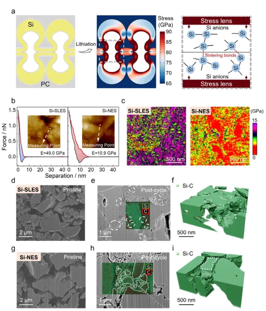
Figure 3. Multi-technique validation of the stress-lens sintering mechanism. (a) Finite element simulation showing lithiation-induced stress concentrated at the high-curvature pore opening region in SLES versus uniformly distributed stress in NES. (b) AFM force-distance curves and Young’s modulus mapping after cycling: SLES interfaces reach 49 GPa modulus with low plastic deformation; NES interfaces show only 10.9 GPa with substantial plastic deformation. (c) Cross-sectional FESEM with EDS before and after one cycle: SLES particles exhibit mutual fusion with minimal cracking; NES particles retain clear boundaries with extensive cracking. (d) FIB-SEM 3D tomographic reconstruction showing the continuous percolating Si network in SLES versus isolated, disconnected particles in NES.
Finite element simulation (Figure 3a) provided the first direct evidence of the stress-lens mechanism: when the Si domain at a pore opening undergoes lithiation, the geometrical constraint of the narrow pore neck concentrates the hoop stress by a factor of more than 5× compared to an unconstrained Si surface. This localized stress concentration drives Si–Si bond rearrangement and interfacial neck formation precisely at the pore opening — the location where interparticle sintering is desired.
AFM mechanical characterization after cycling (Figure 3b) revealed a striking contrast: the SLES sintered interface exhibited a Young’s modulus of 49 GPa, nearly five times the 10.9 GPa measured for the NES interface. The SLES interface also showed significantly lower plastic deformation, indicating that the sintered structure is both stiffer and more resilient to repeated mechanical cycling.
FIB-SEM 3D reconstruction (Figure 3d) provided the most direct visual evidence: the SLES electrode showed a continuous, three-dimensionally percolating Si network with interconnected domains, while the NES electrode consisted of isolated particles with extensive cracking. The carbon coating in NES, rather than protecting the structure, acts as a barrier that prevents the formation of the very sintered connections needed for stable long-range ion transport.
7. Interface Mechanical Reliability and Lithium-Ion Transport
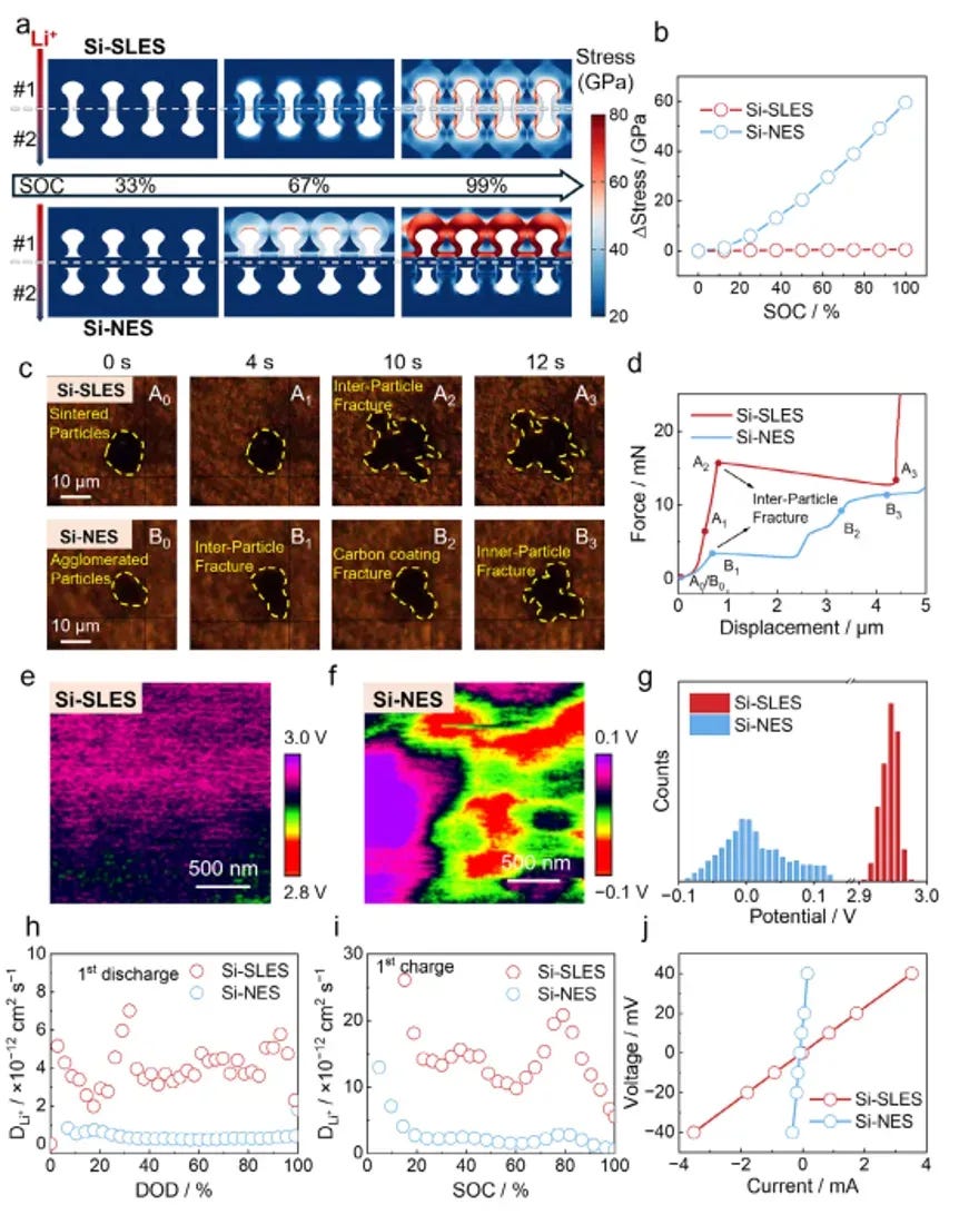
Figure 4. Mechanical reliability and Li⁺ transport of SLES versus NES interfaces. (a) FEM stress distribution at different lithiation states: SLES shows <0.5 GPa interparticle stress difference versus 59.5 GPa for NES. (b) Single-particle indentation fracture test: SLES sintered agglomerate sustains 15.7 mN fracture force (4.6× NES at 3.4 mN). (c) KPFM surface potential mapping showing uniform potential distribution across SLES particle boundaries versus sharp potential drops at NES boundaries. (d) GITT, DC polarization, EIS, and DRT analysis confirming higher Li⁺ diffusion coefficient and lower interfacial resistance for SLES, with stable impedance over cycling.
The mechanical and transport synergy of the SLES design was quantified at the single-particle level. Finite element simulation of stress distribution during lithiation (Figure 4a) showed that the SLES electrode maintains an interparticle stress difference of less than 0.5 GPa — meaning that stress is uniformly distributed across the sintered network. In contrast, the NES electrode exhibits a stress difference exceeding 59.5 GPa, concentrated at the carbon coating interfaces where Li⁺ diffusion is blocked, creating mechanical hot spots that drive coating fracture and particle isolation.
Single-particle testing— a critical measurement for quantifying the mechanical integrity of the sintered interface — was performed using the IEST SPFT2000 Single-Particle Mechanical Testing System. This system applies a controlled compressive load to individual agglomerated particles via a flat diamond indenter, recording the force-displacement curve with ±0.01 mN force accuracy and 10 nm displacement resolution until the particle fractures. The results show that the SLES sintered agglomerate sustains a fracture force of 15.7 mN — 4.6 times higher than the 3.4 mN measured for the carbon-coated NES control. This quantitative difference directly explains why the NES structure suffers from rapid capacity fade: the carbon coating creates a mechanically weak interface that fractures under the stresses of normal cycling, exposing fresh Si surfaces that undergo uncontrolled sintering and exacerbating electrode degradation.
Complementing the mechanical data, KPFM surface potential mapping (Figure 4c) demonstrated that SLES particle boundaries exhibit uniform surface potential distribution with no measurable potential drop, indicating low interfacial resistance. The NES sample, conversely, showed sharp potential drops of 50–80 mV at each particle boundary — direct evidence that the carbon interlayer acts as a resistive barrier to Li⁺ transport. GITT, DC polarization, and EIS-DRT analysis (Figure 4d) confirmed that the Li⁺ diffusion coefficient in SLES is an order of magnitude higher than in NES, and the interfacial impedance remains stable over cycling without the continuous growth that characterizes the NES control.
8. Precise Single-Particle Mechanical Quantification with IEST SPFT2000
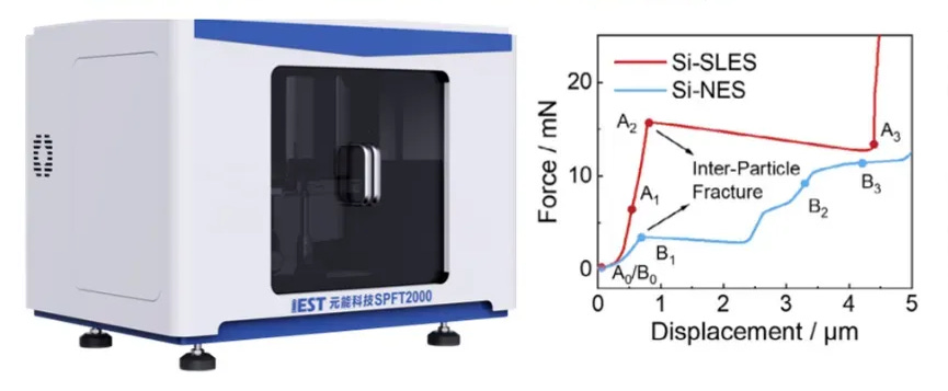
Figure 5. Single-particle mechanical characterization of SLES and NES Si anode particles using the IEST SPFT2000. (left) Schematic of the Single-Particle Mechanical Testing System, (right) Representative force-displacement curves: SLES sintered agglomerate (red) sustains 15.7 mN fracture force with a characteristic multi-stage fracture profile; NES carbon-coated particle (blue) fractures at 3.4 mN with a single brittle fracture event.
The SLES design’s mechanical advantage was quantitatively established through single-particle compression testing on the IEST SPFT2000, an instrument specifically designed for mechanical characterization of individual battery material particles in the 5–50 μm size range, compliant with Chinese national standard GB/T 43091-2023. Key specifications of the system include a force measurement accuracy of ±0.01 mN (0–100 mN range) and ±0.05 mN (0–500 mN range), displacement resolution of 10 nm, and integrated optical imaging at up to 1200× magnification for real-time particle visualization during compression.
Testing was performed on individual agglomerates of the SLES and NES electrodes after one formation cycle. Each particle was centered using the system’s automated XY displacement stage, and a controlled compressive load was applied at a constant displacement rate of 0.5 μm s⁻¹ while the force-displacement curve and optical image were recorded synchronously. The SLES sintered agglomerate exhibited a fracture force of 15.7 mN with a characteristic multi-stage force-displacement profile — initial elastic deformation, followed by micro-cracking events, then final catastrophic fracture. This profile is consistent with a well-sintered, interconnected network structure where mechanical load is distributed across multiple sintered necks before final failure. The NES control, in contrast, showed a single brittle fracture event at only 3.4 mN, with no evidence of load redistribution — consistent with a structure of isolated particles weakly bonded through a brittle carbon coating.
The 4.6× improvement in fracture force provides a direct quantitative explanation for the cycling stability difference between the two architectures: the SLES sintered network resists the mechanical stress of repeated lithiation without fracturing, preserving the percolating ion-transport network over hundreds of cycles. This measurement capability — enabled by the IEST SPFT2000 — turns a qualitative structural hypothesis into a quantifiable mechanical design parameter, providing a methodology that can be extended to other high-volume-change electrode materials such as tin and lithium metal.
9. Electrochemical Performance in Half-Cells and Full Cells
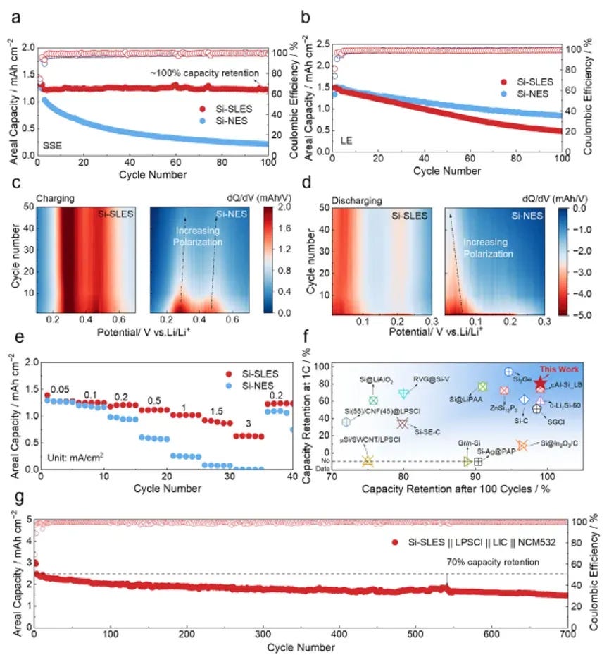
Figure 6. Electrochemical performance of SLES Si anode in sulfide-based ASSBs. (a) Half-cell cycling at 0.2C (100 cycles): SLES retains near-100% capacity; NES retains only 20.6% with continuous decay. (b) dQ/dV contour maps: SLES shows stable polarization without increase over 100 cycles; NES shows progressive polarization growth indicative of increasing interfacial resistance. (c) Rate capability test: SLES delivers 81% capacity retention at 1 mA cm⁻²; NES shows negligible capacity above 0.5 mA cm⁻². (d) Benchmarking against reported Si-based ASSBs: this work achieves the best combination of cycle life and rate performance. (e) Full cell with NCM532 cathode and Li₃InCl₆ electrolyte: 700 cycles with >60% capacity retention.
The SLES silicon anode was evaluated in ASSB half-cells using a Li–In alloy counter electrode, Li₆PS₅Cl solid electrolyte, and a stack pressure of 50 MPa. The results are unambiguous: the SLES anode retains nearly 100% of its initial capacity after 100 cycles at 0.2C, with stable Coulombic efficiency above 99.5% throughout. The NES control, under identical conditions, retains only 20.6% of its initial capacity, with continuous capacity fade from the first cycle onward. The dQ/dV analysis (Figure 6b) reinforces this contrast: the SLES cell shows stable peak positions and intensities over 100 cycles, indicating consistent lithiation/delithiation kinetics and negligible overpotential growth. The NES cell shows progressive peak broadening and shifting, consistent with increasing interfacial resistance and loss of active material contact.
Rate capability testing (Figure 6c) demonstrates that the SLES structure does not compromise high-rate performance for stability. At a current density of 1 mA cm⁻² (corresponding to approximately 1C rate), the SLES anode retains 81% of its low-rate capacity. Even at higher current densities, the SLES anode maintains more than half of its capacity, while the NES anode delivers negligible capacity above 0.5 mA cm⁻². Critically, when the SLES electrode was tested in liquid electrolyte cells, the advantage over NES disappeared — confirming that the SLES strategy is specifically optimized for the all-solid-state configuration, where solid–solid interface stability is the dominant failure mode.
10. Practical Full-Cell Validation: 700 Stable Cycles with NCM532
To demonstrate practical viability, the SLES Si anode was paired with a commercial NCM532 cathode in a full-cell configuration using Li₃InCl₆ as the solid electrolyte. The cell maintained over 60% capacity retention after 700 cycles, with stable voltage profiles and no evidence of sudden failure. This performance places the SLES design among the very best reported for silicon-based all-solid-state full cells, particularly considering that most prior reports are limited to <200–300 cycles before capacity drops below 60%.
The 700-cycle stability is especially significant because it demonstrates that the SLES structure — built in situ during the first cycles — remains mechanically and electrochemically stable over extended cycling. The sintered Si network does not undergo progressive structural degradation; instead, the initial cycling establishes a stable configuration that persists for hundreds of subsequent cycles. This self-limiting characteristic is a direct consequence of the geometry-guided sintering mechanism: once the sintered network is established, the stress concentrations at pore openings dissipate, and the driving force for further sintering diminishes — preventing the uncontrolled over-sintering that would produce oversized agglomerates and electrode fracture.
11. IEST–NanoYang Joint Laboratory at Tianjin University
The collaborative achievement described in this study builds upon a long-standing research partnership between the Nanoyang research group (led by Professor Yang Quanhong at Tianjin University) and IEST Instrument. On March 23, 2026, this partnership was formalized through the establishment of the IEST–NanoYang Joint Laboratory for Advanced Battery Materials Characterization at Tianjin University. The joint laboratory integrates Nanoyang’s frontier mechanism research in carbon-based energy materials with IEST’s precision characterization instruments, providing a dedicated platform for developing and validating next-generation battery material characterization methodologies.
For context on this collaboration, see the official announcement: IEST Instrument and Nanoyang at Tianjin University Establish Joint Laboratory for Advanced Battery Research.
The joint laboratory is strategically positioned to serve as both a showcase for advanced testing instrumentation in the northern China market and as a critical support platform for translating fundamental scientific discoveries into industrial-scale battery solutions. The SLES study represents a direct outcome of this academia-industry synergy: Nanoyang’s deep understanding of carbon material geometry and interfacial electrochemistry, combined with IEST‘s precision single-particle mechanical testing capability, produced the quantitative mechanical evidence that distinguishes SLES from prior static-constraint approaches.
12. Conclusions and Outlook
This work demonstrates that electrochemical sintering — conventionally regarded as a detrimental side reaction in silicon anodes — can be harnessed as a constructive process through precise geometric design at the microscale. The SLES strategy uses porous carbon with high-curvature pore openings as stress concentrators that selectively direct lithiation-induced mechanical stress to particle contact points, inducing controlled, local electrochemical sintering that builds a continuous, mechanically robust, and ionically conductive Si network while preserving internal void volume for volume expansion buffering.
Key quantitative achievements include:
Interface modulus: 49 GPa (SLES) vs. 10.9 GPa (NES) — a 4.5× improvement in interfacial stiffness.
Interparticle stress uniformity: <0.5 GPa (SLES) vs. 59.5 GPa (NES) — stress is uniformly distributed across the sintered network.
Single-particle fracture force: 15.7 mN (SLES) vs. 3.4 mN (NES) — a 4.6× improvement, measured on the IEST SPFT2000.
Half-cell capacity retention: ~100% after 100 cycles at 0.2C.
Rate capability: 81% capacity retention at 1 mA cm⁻².
Full-cell stability: >60% capacity retention after 700 cycles with NCM532 cathode.
The “geometry-guided dynamic evolution” design philosophy demonstrated here has broad applicability beyond silicon anodes. The same principle of using geometric constrictions to concentrate and direct mechanical stress during electrochemical cycling can be extended to other high-volume-change anodes for all-solid-state batteries, including tin (Sn) and lithium metal, offering a generalized pathway toward stable, high-energy-density solid-state energy storage.
🔬 Evaluate Your Silicon Anode Particle Strength with IEST SPFT2000
Quantify single-particle fracture force, crushing strength, and interfacial mechanical properties for your silicon-carbon, hard carbon, or solid electrolyte materials. The IEST SPFT2000 provides ±0.01 mN force accuracy, 10 nm displacement resolution, and compliance with GB/T 43091-2023.
Also explore our comprehensive Solid-State Battery Testing Solutions for multi-dimensional characterization.
Need high-precision structural data for your R&D? Talk to our engineers:
This article was originally published at: Advanced Materials: Electrochemical Sintering Enables Stress-Lensed Silicon Anodes for Long-Life All-Solid-State Batteries Validated by IEST SPFT2000 first appeared on IEST Instrument | World-leading Innovative Lithium Battery Tester Solution Provider